2000
Sketchy plans were being formulated for RAF Kinloss to build a "Robotwars" style robot for an exhibition at the NEC, Birmingham, England. No word on budget and rules. Four original team members were recruited and responsibilities assigned.
Without the budget it was difficult to make concrete plans.
Ideas for a weapon were discussed and it was decided that an axe weapon would be built. The designer of the weapon, a physicist, lives at the other end of the country so correspondence was by e-mail and letter. Tim contacted the weapon designer and offered to build his design.
2000
2000
These are:
2000
2000
2000
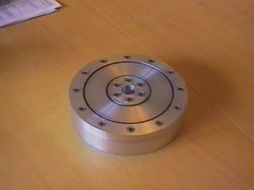
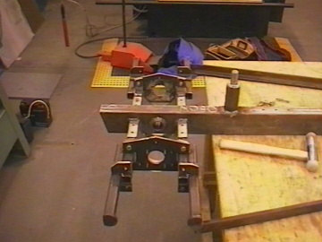
The gearboxes arrive from HPC. We were worried that the gearboxes wouldn't take much longitudinal load. We decide to enclose the output shaft between two bearing carriers.
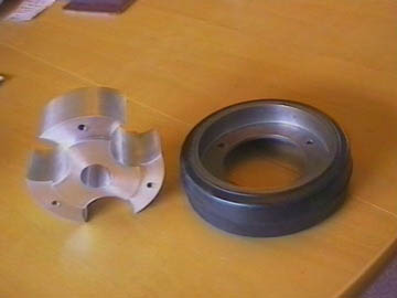
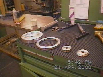
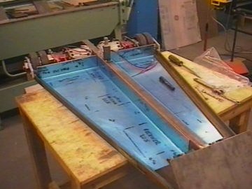
The first photograph shows the drive components laid out pre-machining, The spine is made of 80mm x 40mm x 3mm steel box section! Later on we weld cups for the motors bearing carriers to sit in. Square holes are milled into the spine for the 1" box section. Note the masking tape around the motors. Very important this, permanent magnet motors are great at picking up swarf.
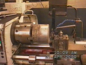
The motors had to be modified. The 12mm shaft was turned down to 9mm for the gearbox. This was a mistake, especially since there isn't any flexibility in the drive. Longer bolts were welded in the motor cover and the Dangerous Machines suppression boards fitted.
All of the components have arrived for the weapon. Its clear that we've bitten off more than we can chew. It took about 14 hours to machine two drive bearing carriers. With 24 different components to machine, making them up on the fly from basic drawings we decide to cut our losses and concentrate on the drive. Turning up at the NEC with a bag of bits would not do!
Additional orders for Anvils weapon made. 2 x 50t & 2 x 20t mod 2.5 EN36 case hardened gears ordered from HPC. One additional NCC 24-70 ordered for the weapon/drive spare. And finally a 40:1 gearbox from Davall.
2000
It became obvious that the weapon would have to be shelved since time was running out fast. We also decided not to worry about the 80kg weight limit.
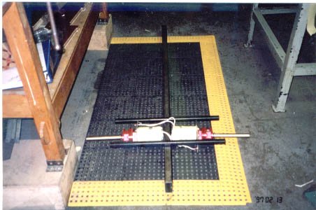
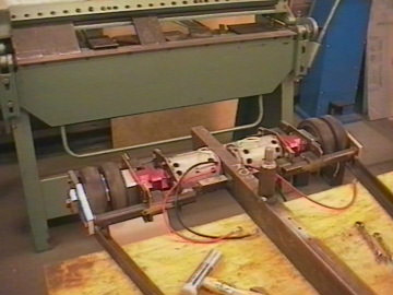
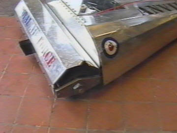
Checkout the outer bearing carrier on the drive assembly, 10mm Aluminum plate, and the battery clamp must weigh a kilo on its own!
The motor cables were replaced because the insulation is very thin and has a tendancy to tear, insulation similar to HT leads.
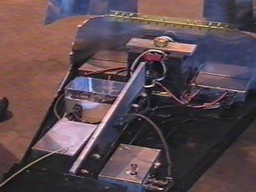
Military spec cable looms constructed and electronics assembled. Anvil's electronics are very simple with a couple of differences to standard Robotwars competitors. To guard against RF noise interfering with the receiver, the motors were suppressed and the receiver was isolated from the robot's chassis. The output from the receiver was optoisolated from the servos and each servo signal was individually screened. RF1 safetys supplied by the builder of series 3 winner, Chaos 2 fitted. Separate supplies for the receiver, servos and motors are present on Anvil. This ensured that the robot could work virtually all day long with just the main drive batteries to be replaced if required.
The mixing is done by speed/steer servos driving pots which in turn drive the 4QD mixing board. This is the quickest and easiest method of mixing. It worked well for us.
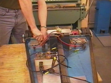
All of the components were boxed within cast aluminium enclosures from RS. The speed controllers were thermally bonded using heatsink compound to the enclosures and the floorpan. The chassis is now one big heat sink.
During the setting up of the controllers an oscilloscope probe earth lead is dropped onto the track side of the controller. Diasaster, one fried NCC24-70. Thankfully we had a spare for the weapon. 4QD repaired the board very quickly for a flat fee of �15.
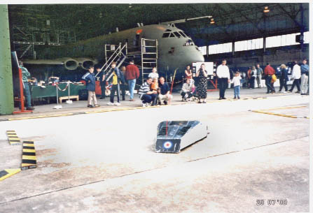
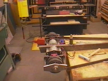
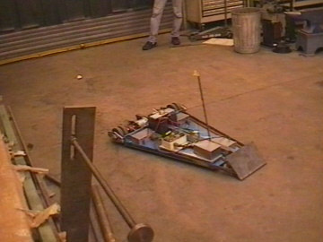
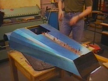
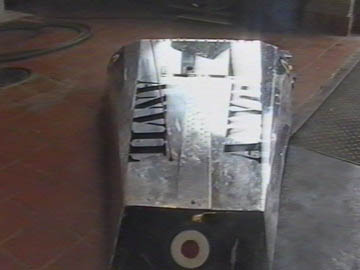
It lives! Shown here driving round the welding bay with a piece of paxolin rod holding up the aerial. Even now it becomes evident that aerial siting is crucial. This is the first robot we've constructed and we are surprised at the power. We struggled to lift the robot through the welding bay door. We begin to wonder exactly how much this beast weighs.
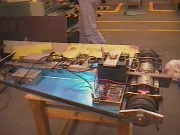
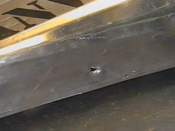
Outer skin is constructed from 18swg aluminium. It looks the business but not really up to stopping impact weapons.
Lexan isolator cover fitted and isolator fitted to chassis.
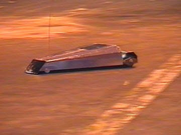
Testing starts and we start to breathe a bit more easily. Now our thoughts are with the opposition and reliability. Final weight by some miracle is 80kg.
2000
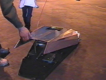
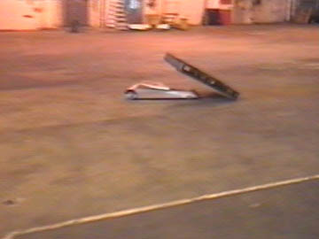
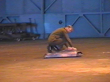
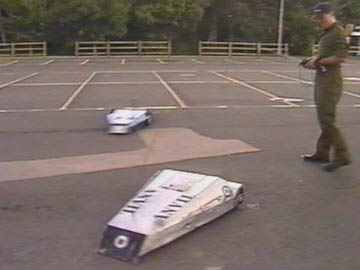
We arrive at the NEC and find a tiny arena, not suitable for robotic combat. We allow the public to drive the robot around a mini course after we turn down the gain of the controllers. This has the effect of reducing speed but also makes the robot more sluggish. Anvil is still more than capable of breaching the arena so the cut off switch on the transmitter is very useful when kids get the 'Red Mist'.
We see the opposition for the first time. The Royal Navy's robot is constructed from quarter plate and powered by Sinclair C5 motors. Its weapon is the ability to spin on the spot at high speed and to articulate the height adjustable blade into the opponent. It weighs a hefty 85kg and definitely has the potential to inflict serious damage on Anvil.
Disaster! We sheared a motor drive shaft after driving into a kerb. Turning the shaft from 12mm to 9mm now seems like a bit of a daft idea. We manage bore, pin and silver solder the shaft as a temporary repair.
BATTLE
Fortunately for us the Navy's robot suffered from poor control and limited range. Anvil was able to manoeuvre precisely and attack at will, although the only hope of inflicting damage was by flipping him or by damaging the wheels.
Flipping would be very difficult since the two halves of the body are hinged, our scoop wasn't really suitable for flipping this design of robot. Even when flipped it could probably still operate, although the 'rubber duck' style aerial looked like it would be trashed very quickly upside down.
The Navy's robot punctured Anvils skin several times and our drive shaft gave out again giving us intermittent ability to travel in a straight line, but we claimed victory on the basis of aggression and good looks!
2000
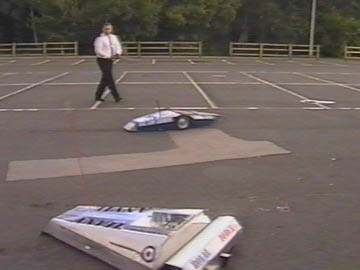
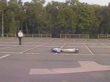
Anvil's next outing was at the RAF Kinloss families day. The motor spindle sheared twice during the day, but we got quite good at quick repairs.
When we put Anvil to bed that night we left the power on, as it had been a long day and we wanted to discharge the batteries. When we came back in the morning, Anvil had taken a trip around the workshop (no damage to robot or workshop somehow). This highlighted a problem with the failsafes. Combined with the shearing motor spindle, it became obvious that Anvil would need a major rebuild.